Hydraulic System Design: Choosing Fittings and Flanges
HGW Hydraulics on Apr 6th 2021

Quick answer
Hydraulic system design should choose fittings and flanges around pressure, seal reliability, routing, maintenance access, vibration, temperature, and the mating components already specified. The easiest fitting to buy is not always the best fitting to design into a system.
Designers and maintenance buyers should separate removable service connections from permanent joints, then choose the connection family that protects uptime without creating leak paths.
Why removable fittings matter in hydraulic design
Most hydraulic systems need service access. Pumps, valves, cylinders, filters, test points, hoses, and manifolds may need to be removed or replaced. Fittings and flanges provide that access, but each removable joint is also a possible leak point.
The design goal is to use the right number of serviceable connections, not the maximum number. Place them where maintenance is realistic and avoid creating tight bends or hard-to-inspect joints.
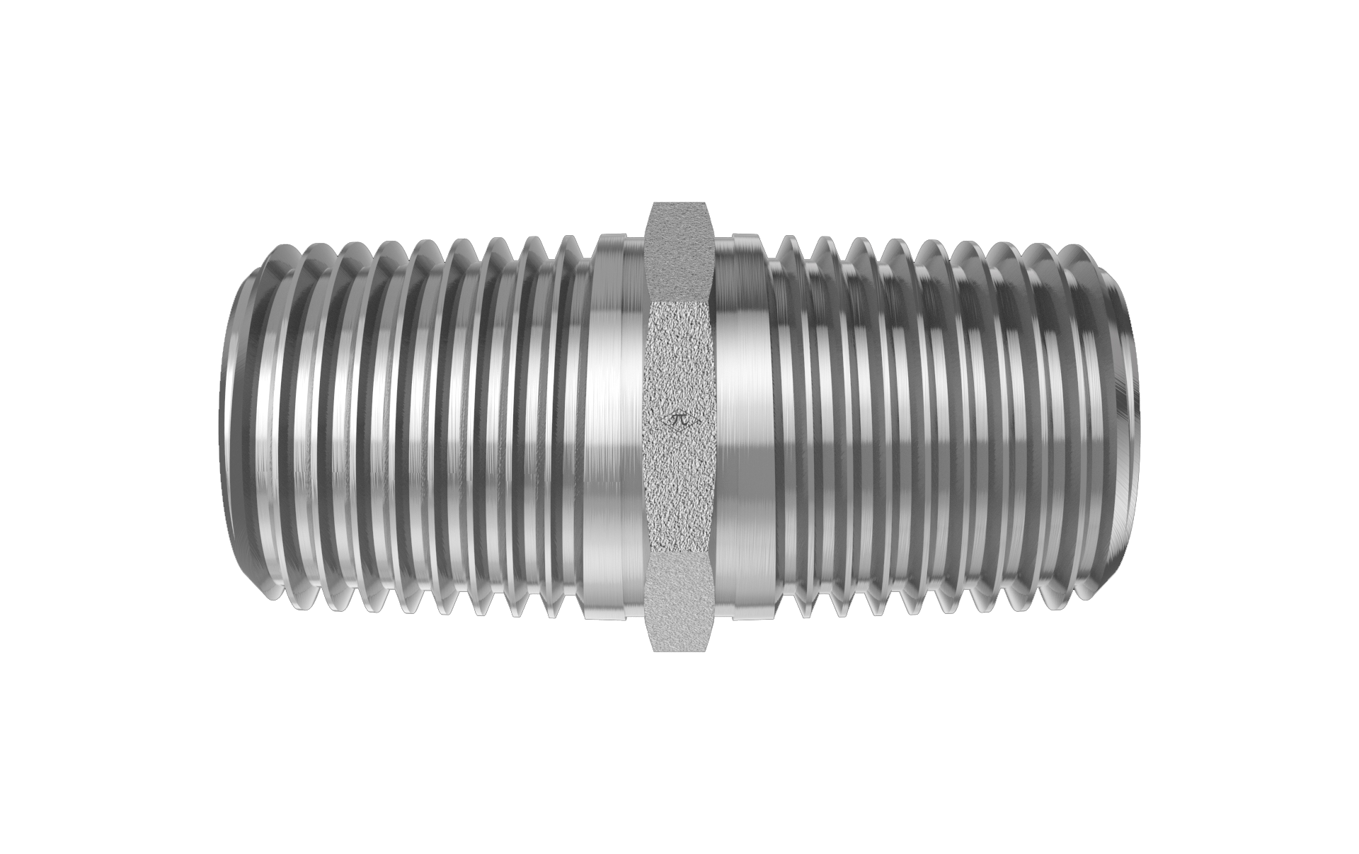
Avoid over-reliance on metal pipe threads
Tapered metal pipe threads can work in many settings, but they are easy to over-tighten and may loosen under temperature change or vibration. They also depend on correct sealant practice. When a system needs repeatable assembly or cleaner sealing, designers often consider JIC, ORB, ORFS, metric, or flange alternatives.
If pipe threads are used, design enough clearance for proper wrenching and inspection. Do not hide a pipe-thread joint where a leak would be hard to find.
Where flanges belong
Flange connections are useful for larger lines, high flow, higher pressure, or places where threaded connections would be difficult to assemble. SAE Code 61 and Code 62 flange patterns are not interchangeable. The bolt pattern, pressure class, face, O-ring, and hardware all matter.
During design, check hose movement, alignment, bolt access, seal compression, and whether the line can be serviced without forcing the flange halves together.
HGW categories to compare
For compact hydraulic lines, compare 37 degree JIC fittings, SAE O-ring boss fittings, and ORFS fittings. For heavier flange work, use flange adapters and plugs. For imported equipment, check Metric / DIN 2353 and BSP categories.
A good design record should include connection standard, pressure class, tube or hose size, body angle, material, finish, and the reason that connection was chosen.
FAQ
Should a hydraulic system use pipe threads everywhere?
No. Pipe threads can be useful, but repeated service, vibration, cleanliness, and leak control may point to JIC, ORB, ORFS, metric, or flange connections.
What is the biggest flange design mistake?
Mixing pressure classes or forcing misaligned flange halves together. Confirm Code 61 versus Code 62, bolt pattern, seal condition, and line alignment.
What should be recorded in the design file?
Record the connection family, size, pressure class, material, seal, body style, installed orientation, and service access requirement.